The Blogs Aim
Its 30 degrees Centigrade in the back yard and the pot grown beans and tomatoes and cucumbers get mighty thirsty.
Whilst we are not covered by the drought order in sunny Emsworth on the Hampshire coast, I do not like wasting water or carting the watering can around each night and morning.
So we have invested in a Hozelock drip irrigation system on a tap timer, we have used these systems at another house we lived in and they work well.
However they do suffer from a propensity of the feed hose from the tap becoming detached from the hose connection to the drip feed system.
This never happens with any warning sign and usually dumps great quantities of precious water in a place that does no good (floods of biblical proportions have occurred in the past).
Well it happened last week again and enough is enough.
Technology to the rescue but on the cheap.
Got a lovely second hand BRITA water flow meter on E-bay with a pulse output for every 10L flow through it.
This has been plumbed hard onto the garden tap thread, so I now have a pulse for every 10L flowing (pulse is a passive momentary contact).
Now comes the technology:- feed the pulse to a micro processor I/O input and write an algorithm to
1) Build up a profile for flow with the drip feed running or the hose in use.
2) Tune the algorithm to raise an alarm when the flow is to high for too long.
As I might be away when the next flood occurs I want to be able to turn off the water flow.
So the alarm has to be fed into a stop down valve.
Here is the rub motorised battery powered stop valves cost an arm and a leg and low voltage flow solenoids take to much current to be battery operated. (Unless some one knows different).
However I have a way around this tap timers now sold for garden irrigation (and the cause of my problem) have come down to sub £20 in value.
These are very nifty bits of mechanical and plumbing engineering working on a couple of 1.5 volt cells, they have a purpose built rotating ball valve controlling the flow and it only draws current when opening or closing.
I seem unable to find this valve assembly from an original equipment supply (first time China and India have let me down), however good old e-bay has sourced a cheap tap timer (probably made in Hong Kong under license).
This is going to be hacked when it arrives and connect to the water flowing alarm.
Will it all work?
Keep looking as I post the ups and downs of my mad idea.
“There’s a lot more goodies in the pipe line” to quote 10CC and now the electronics den is back together I hope to be posting and updating my blogs more regularly.
Proof of concept.
Been a bit slow with this update, which is mainly down to having to finish decorating the stairs to the bedrooms which allow access to my attic electronics workroom.
However much has been going wrong and right while the decorating took place.
Royal Mail has delivered my garden water timer purchased from E-Bay, nice unit seems a shame to start to dismantle it, but we must boldly go were others fear to tread.

Hose timer as sold on EBay
First remove the grey battery case, this reveals two case screws, which can be removed with a long thin Philips head screw driver. However the top of the case will not budge. The green plastic must be cut at the top to reveal the third and final Philips screw.

Three screws later and the water timer is partially deconstructed
Three screws removed shows the connections to the battery pack 2AA cells meaning the unit will run from 3 volts down to about 2. 5 Volts. The little motor and gear box flip the valve open and closed. The Green PCB hides a microprocessor and rotary position switches which control the motor through a discrete six transistor H-Bridge motor control.

Close up of valve and motor actuator
Close up of the lower housing with motor (black lump). The top white gear driven from the cog on the motor spindle turns through 180 degrees of rotation, before hitting a stop at the end of travell. It appears that the motor is pulsed for a small time sufficient to rotate the white main gear from one stop to the other but short enough that when the motor is stalled at the end of travell that the curent drawn in stall does not burn out anything.

Hacking the electronics for a proof of concept
This picture shows the other side of the PCB with the minute switch removed. Desoldering the switch is not a task for a beginner and the desoldering iron is heavily used to achieve this state. Well worth the effort as I am now able to connect in turn the on and off switch pads to the negative and positive power rails and activate the motor to open and close the valve at my command.
Now I have got this far the thought of trying to tack my Atmel ATtiny85 processor onto the existing PCB seems to be an ugly patch too far, especially as I have started to think that this valve unit can be adapted to a greenhouse misting system, by adding a humidity sensor and changing some code in the processor.
So what next build a new circuit.
Now I hate to design and build a PCB at concept stage and over the years I have found a simple set of programmes that allow me to breadboard a circuit on Vero Board (strip board). I started my commercial electronics carrer using Vero Board so I am happy working with it. However a lot of time a heartache can be saved using veeCad this is like a PCB layout programme for stripboard and works well with TinyCad schematic drawing programme.
Things had gone well up to this point.
I have long ago gravitated to Mac OSX as it is very resilient and almost virus free, but still the majority of electronics type programmes are Windows based.
So I started up my Vaio widows laptop and found that everything had been updated since I last used Windows, veeCad and TinyCad, so wait for the downloads and essential reboots.
Strange as it may seem I know about H-Bridges for controling a motor but have never used an H-Bridge chip or built a descrete transistor H-Bridge. After a couple of hours of browsing the net I have the descrete transistor bridge design I want (http//library.solarbotics.net/circuits/driver_tilden.html).
This is when the air turns blue.
Well not the air but me.
With my move from London to rural Hampshire (England) refurbishing our tired 1963 chalet bungalow has taken close on 18 months and left little time for electronics. As a result it has been close on two years since I used the two bits of software quoted above, honestly put I had forgotten that a three legged transistor can be assigned 1,2 or 3 for its legs so of course when I used the programme to draw the electronic schematic I forgot to check that the Veroboard layout might have assigned different numbers to the transistor legs. I nearly always lay up the links on the Veroboard first before inserting the components, so it was an hours work before I fitted the first two transistors and realised at this point they were not orientated the right way. So I had to dive into the two software packages and put their pin structures right. So start again with a new bit of board and a whole new set of links.
Having cut all the copper tracks in the right place and soldered in all the links and the components (except the microprocessor chip) it’s now time to connect the circuit up to the lab bench power supply. These are a boon as you can set the voltage required to run the circuit but with minimal current set. By doing this it is usually possible to slowly turn up the current supply to the circuit and check to see if an abnormal amount of current is flowing, which usually means a short or a bad positioning of a link. Alls well the current stabalises at almost nothing. Now we can connect the motor to the bridge outputs and to my great glee no current flowing. Next a very crude technique in the prototype test arsenal take a wire and touch it to one of the inputs of the H-Bridge and the positive supply very briefly. Oh what joy motor turns gear wheel with a resounding clonk as it hits the end stop. Using the wire on the other input to the H-Bridge causes the motor to turn with a very satisfying clonk in the other direction.
We are on our way.

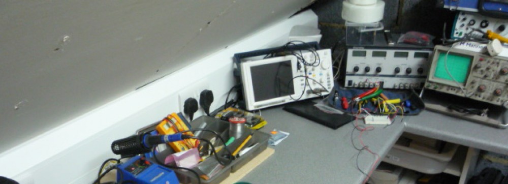
Fabrication bench in attic workshop
The fabrication bench in a state that is tidy!!, like cooking the bench has to be cleaned down before testing begins ranged on the right are a digital and analogue oscilloscope and the bench power supply.
The multimeter in the tray is cheap and disposable. I can connect it up badly during testing and loss is minimal cost.

Prototype H-Bridge control with Atmel ATTiny85 chip in place

- Test unit with plumbing connectors assembled

Test circuit may look a little ragged but I only need it to prove that the concept design will work. The grey connector on the right is for programming the chip in the center. White and mauve leads go to the motor on the valve and the red and black to the bench power supply set at 2.7 volts to test everything will work on 2 AA cells that are well discharged.
A look at the plumbing the brass female socket on the left was difficult to find as I kept looking for a coupler and not a socket, once the syntax was correct any number were available the middle connection is made with a male to male hydraulics coupler. all fittings are 3/4 inch BSP (British Standard Pipe).
On test last night and I had the motor cycling back and forth under the control of processor surprisingly the motor is only being activated for 50 microseconds to get it to travel to the end stop in each direction. Have not measured the instantaneous current but bench supply shows around 68 milliamps drawn, this is such a short duration the batteries should last a long time. Standby current is about 3 milliamps and I should be able to get this down to a few microamps by putting the microprocessor to sleep for most of the time.
Hydraulic testing will now have to wait while I have a few days doing some new jobs that have become critical in the bungalow.
However I can now start to work on the final pretty PCB that most people now associate with commercial electronics. I like the idea of the two rotary switches for setting up the water alarm cut off parameters. One will set the flow rate say 10 liters to some other higher figure of liters, the other will set the amount of time in minutes that the set flow can run for, 10 minutes to some higher minute figure. Both switches will have ten stages.
Would it be worth having a display? The next prototype will so I can get debugging information . As I am using a water meter as the flow meter this has the total water consumed, but if I integrate a black box electronic flow meter into the final design then total flow would not be known. Who would the users be? If this went to market in today’s water shortage and water price hikes I suspect most buyers would like total water usage information.
Comment so far are welcomed and if you have extra ideas I will try to combine them.
So long for now.
